User:Hg200
OpenGL coordinate systems
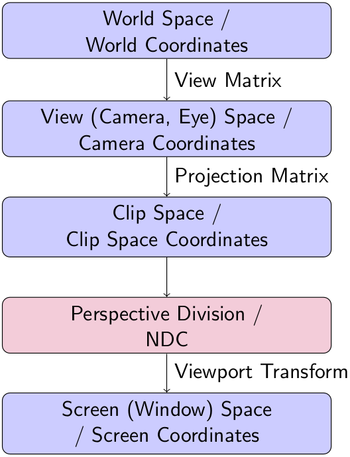
In the Octave plotting backend, we find various OpenGL transformations. Some of the classic OpenGL transformation steps, as well as coordinate systems, are shown in the following picture:
The Octave coordinate system
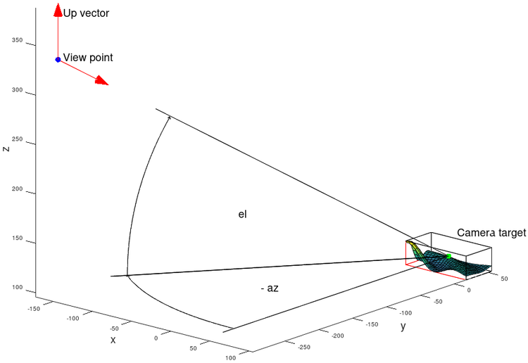
In Octave a plot scene is defined by a "view point", a "camera target" and an "up vector".
update_camera()
In the second part of "axes::properties::update_camera ()" the view transformation "x_gl_mat1" and projection matrix "x_gl_mat2" are put together. The following chapter illustrates some of the properties of "x_gl_mat1" and "x_gl_mat2".
The role of "x_gl_mat1"
x_view
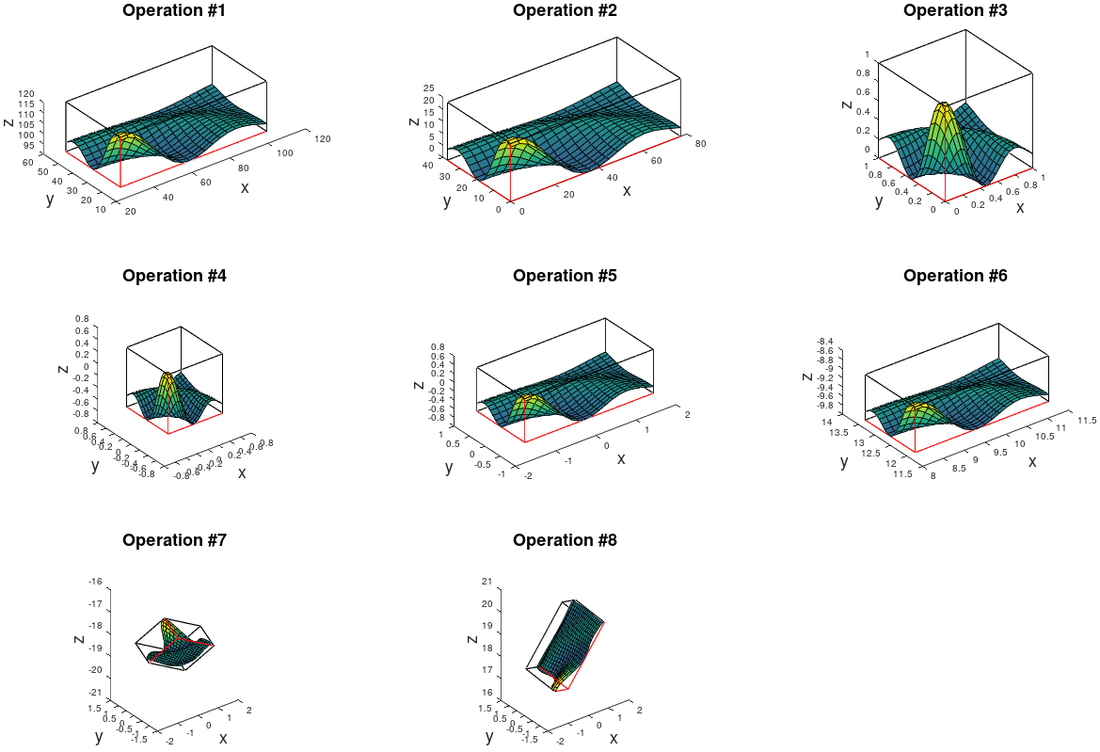
The following section of code composes the matrix "x_view", which is a major subset of "x_gl_mat1". The matrix "x_gl_mat1" consists of multiple translations, scales and one rotation operation. The individual operation steps are shown in a picture below.
| Code: Section of axes::properties::update_camera ()" |
  // Unit length vector for direction of view "f" and up vector "UP"
  ColumnVector F (c_center), f (F), UP (c_upv);
  normalize (f);
  normalize (UP);

  // Scale "UP" vector, so that norm(f x UP) becomes 1
  if (std::abs (dot (f, UP)) > 1e-15)
    {
      double fa = 1 / sqrt (1 - f(2)*f(2));
      scale (UP, fa, fa, fa);
    }

  // Calculate the vector rejection UP onto f
  // s, f and u are used to assemble the rotation matrix l
  ColumnVector s = cross (f, UP);
  ColumnVector u = cross (s, f);

  // Construct a 4x4 matrix "x_view" that is a subset of "x_gl_mat1"
  // Start with identity I = [1,0,0,0; 0,1,0,0; 0,0,1,0; 0,0,0,1]
  Matrix x_view = xform_matrix ();
  // Step #7 -> #8
  scale (x_view, 1, 1, -1);
  Matrix l = xform_matrix ();
  l(0,0) = s(0); l(0,1) = s(1); l(0,2) = s(2);
  l(1,0) = u(0); l(1,1) = u(1); l(1,2) = u(2);
  l(2,0) = -f(0); l(2,1) = -f(1); l(2,2) = -f(2);
  // Step #6 -> #7 (rotate on the Z axis)
  x_view = x_view * l;
  // Step #5 -> #6
  translate (x_view, -c_eye(0), -c_eye(1), -c_eye(2));
  // Step #4 -> #5
  scale (x_view, pb(0), pb(1), pb(2));
  // Step #3 -> #4
  translate (x_view, -0.5, -0.5, -0.5);
|
x_gl_mat1
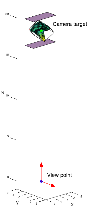
To visualize the matrix properties, the "x_gl_mat1" matrix is multiplied by the object coordinates. After the transformation, the plot box is aligned with the Z-axis and the view point is at the origin . The matrix transforms world coordinates into camera coordinates. The purple planes show the near and far clipping planes.
The individual translation, scaling and rotation operations of "x_gl_mat1", are shown in the following figure:
The role of "x_gl_mat2"
Bounding box
The matrix "x_gl_mat2" is composed of the sub matrices "x_viewport" and "x_projection". The purpose of these matrices is to fit the associated 2D image of the above transformation result into a "bounding box". The bounding box is defined as follows:
- bb(0), bb(1): Position of the "viewport"
- bb(2), bb(3): Width and height of the "viewport"
Hint: If you debug in "update_camera ()", you can print "bb":
 (gdb) print *bb.rep.data@bb.rep.len
 (gdb) $1 = {72.79, 31.50, 434, 342.29}
Compare the result with the output on the Octave prompt:
 hax = axes ();
 get (hax, "position")
 ans = 73.80 47.20 434.00 342.30
 get (gcf, 'position')
 ans = 22 300 560 420
Where 420 - 342.30 - 31.5 + 1 = 47.20
x_projection
In the following simplified code section the matrix "x_projection" is composed. It is used to normalize the image of the above transformation. For this purpose, the field of view (FOV) must be calculated:
| Code: Section of axes::properties::update_camera ()" |
  if (cameraviewanglemode_is ("auto"))
    {
      if ((bb(2)/bb(3)) > (xM/yM))
        // When the image is scaled to the size of the bounding box,
        // the height collides with the bounding box first. Therefore,
        // the camera view angle is defined by the image height yM.
        af = 1.0 / yM;
      else
        // The image width collides with the bounding box.
        af = 1.0 / xM;

      // The view angle "v_angle", also called field of view "FOV",
      // is formed by the hypotenuse and the adjacent side, which is given by
      // the distance between the view point and the camera target "norm (F)".
      // The ratio of the opposite side, given by "af", to the adjacent side in
      // a right-angled triangle is the tangent of the view angle.
      v_angle = 2 * (180.0 / M_PI) * atan (1 / (2 * af * norm (F)));
      cameraviewangle = v_angle;
    }
  else
    v_angle = get_cameraviewangle ();

  // x_projection: identity "diag([1, 1, 1, 1])"
  Matrix x_projection = xform_matrix ();
  // Calculate backwards from the angle to the ratio. This step
  // is necessary because "v_angle" can be set manually.
  double pf = 1 / (2 * tan ((v_angle / 2) * M_PI / 180.0) * norm (F));
  // Normalize to one. Resulting coordinates are "normalized device coordinates".
  scale (x_projection, pf, pf, 1);
|
x_viewport
"x_viewport" is a transformation used to place the previously "normalized" plot box in the center and to fit it tightly into the bounding box:
| Code: Section of axes::properties::update_camera ()" |
  double pix = 1;
  if (autocam)
    {
      if ((bb(2)/bb(3)) > (xM/yM))
        pix = bb(3);
      else
        pix = bb(2);
    }
  else
    pix = (bb(2) < bb(3) ? bb(2) : bb(3));

  // x_viewport: identity "diag([1, 1, 1, 1])"
  Matrix x_viewport = xform_matrix ();
  // Move to the center of the bounding box inside the figure.
  translate (x_viewport, bb(0)+bb(2)/2, bb(1)+bb(3)/2, 0);
  // Scale either to width or height, to fit correctly into the bounding box
  scale (x_viewport, pix, -pix, 1);

  x_gl_mat2 = x_viewport * x_projection;
|
Note: The matrix "x_gl_mat2" scales x, y. However the z-coordinate is not modified!
setup_opengl_transformation ()
OpenGL backend
In the OpenGL backend, the view matrix, an orthographic matrix, and the viewport transform are used to transform the octave plot into the screen window.
| Code: Section of opengl_renderer::setup_opengl_transformation ()" |
  Matrix x_zlim = props.get_transform_zlim ();

  xZ1 = x_zlim(0)-(x_zlim(1)-x_zlim(0))/2;
  xZ2 = x_zlim(1)+(x_zlim(1)-x_zlim(0))/2;

  // Load x_gl_mat1 and x_gl_mat2
  Matrix x_mat1 = props.get_opengl_matrix_1 ();
  Matrix x_mat2 = props.get_opengl_matrix_2 ();

  m_glfcns.glMatrixMode (GL_MODELVIEW);
  m_glfcns.glLoadIdentity ();
  m_glfcns.glScaled (1, 1, -1);
  // Matrix x_gl_mat1
  m_glfcns.glMultMatrixd (x_mat1.data ());
  m_glfcns.glMatrixMode (GL_PROJECTION);
  m_glfcns.glLoadIdentity ();

  Matrix vp = get_viewport_scaled ();
  // Install orthographic projection matrix with viewport
  // setting "0, vp(2), vp(3), 0" and near / far values "xZ1, xZ2"
  m_glfcns.glOrtho (0, vp(2), vp(3), 0, xZ1, xZ2);
  // Matrix x_gl_mat2
  m_glfcns.glMultMatrixd (x_mat2.data ());
  m_glfcns.glMatrixMode (GL_MODELVIEW);

  m_glfcns.glClear (GL_DEPTH_BUFFER_BIT);
|
Hint: If you debug in "setup_opengl_transformation ()", you can print the viewport "vp":
 (gdb) print *vp.rep.data@vp.rep.len
 (gdb) $1 = {0, 0, 560, 420}
This is consistent with the window size.


![{\textstyle [0,0,0]}](https://wikimedia.org/api/rest_v1/media/math/render/svg/ced759f6efbc47419d3fda1d17d8dfbeeb822b85)

